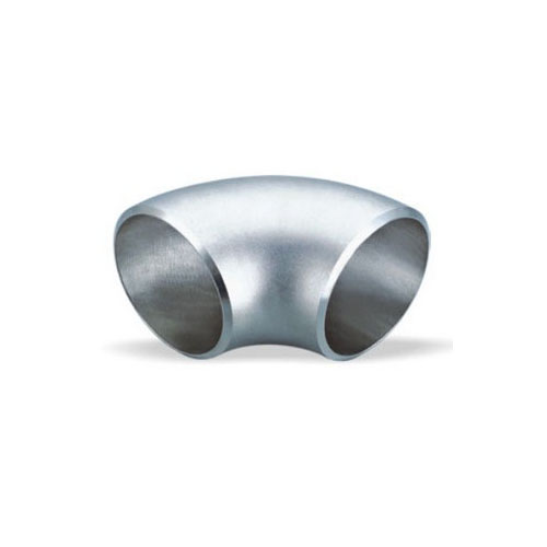
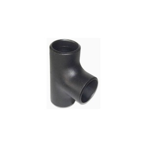
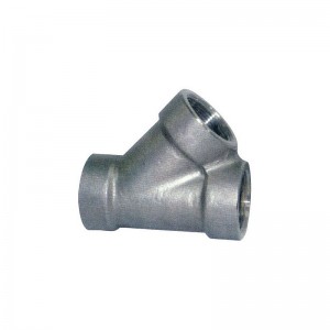
Steel Butt Welding Pipe Fittings 45 Degree Elbow
45 Degree Elbow
Material: Carbon Steel, Stainless Steel, Alloy Steel
Technical: Forged and pushing
Connection: Welding
Standard: ANSI, ASME,AP15L,DIN,JIS,BS,GB
Type: 45°and 90°LR/SR Elbow, Reducers, Tee, Bends, Cap, Cross.
Wall Thickness: SCH5-SCH160 XS XXS STD
Surface: Black Paint/Rust-proof Oil/Hot Dipped Galvanized
Angles: 30/45/60/90/180°
Size: 1/2”-80”/DN15-DN2000
Certificate: ISO -9001:2000, API, CCS
Application: Chemical Industry, Petroleum Industry, Construction Industry and Other
Inspection: Factory In-House Check or The Third Party Inspection
Packing: Plywood Pallets/ Wooden Case Or As Per your Specification
Elbow is a pipe fitting that changes the direction of the pipeline in the pipeline system. According to the angle, there are three most commonly used elbows: 45 ° and 90 ° 180 °, and other abnormal angle elbows such as 60 ° are also included according to the needs of the project. Elbow materials include cast iron, stainless steel, alloy steel, malleable cast iron, carbon steel, non-ferrous metals and plastics. The connection methods with pipes include: direct welding (the most commonly used method) flange connection, hot-melt connection, electric fusion connection, threaded connection and socket connection. According to the production process, it can be divided into: welding elbow, stamping elbow, push elbow, casting elbow, etc. other names: 90 degree elbow, right angle bend, love bend, etc.
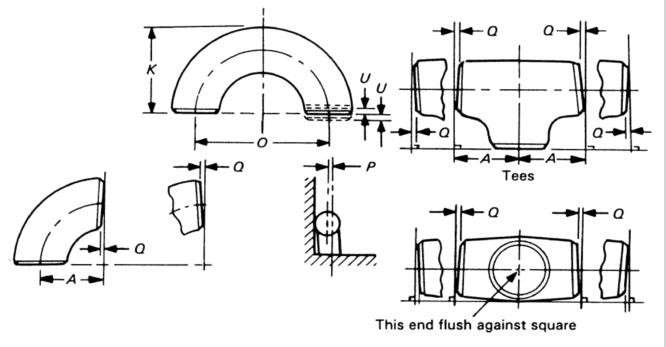
ASME B16.9, B16.28
|
Pipe Size |
All Fittings |
90 & 45 Elbows and Tees |
Reducers and Lap Joint Stub ends |
Caps |
|||||||
|
|
Outside Diameter at Bevel, D (1) |
Inside Diameter at End (1) |
Wall Thickness t |
Center-to-End Dimensions A,B,C,M |
Overall Length, F,H |
|
|||||
|
|
|
|
|
|
|
Overall Length, E |
|||||
|
|
|
|
|
|
|
|
|||||
|
|
IN |
MM |
IN |
MM |
|
IN |
MM |
IN |
MM |
IN |
MM |
|
½ ~ 2½ |
+0.06 |
+1.6 |
±0.03 |
±0.8 |
Not Less Than 87.5% of Nominal Thickness |
±0.06 |
±2 |
±0.06 |
±2 |
±0.12 |
±3 |
|
|
-0.03 |
-0.8 |
|
|
|
|
|
|
|
|
|
|
3 ~ 2½ |
±0.06 |
±1.6 |
±0.06 |
±1.6 |
|
|
|
|
|
|
|
|
4 |
|
|
|
|
|
|
|
|
|
|
|
|
5 ~ 8 |
+0.09 |
+2.4 |
|
|
|
|
|
|
|
±0.25 |
±6 |
|
|
-0.06 |
-1.6 |
|
|
|
|
|
|
|
|
|
|
10 ~ 18 |
+0.16 |
+4.0 |
±0.12 |
±3.2 |
|
±0.09 |
|
±0.09 |
|
|
|
|
|
-0.12 |
-3.2 |
|
|
|
|
|
|
|
|
|
|
20 ~ 24 |
+0.25 -0.19 |
+6.4 -4.8 |
±0.19 |
±4.8 |
|
|
|
|
|
|
|
|
26 ~ 30 |
|
|
|
|
|
±0.12 |
±3 |
±0.19 |
±5 |
±0.38 |
±10 |
|
|
|
|
|
|
|
|
|
|
|
|
|
|
32 ~ 48 |
|
|
|
|
|
±0.19 |
±5 |
|
|
|
|
|
Pipe Size |
Lap Joint Stub Ends (2) |
180 Return Bends |
||||||||||
|
|
Outside Diameter of Lap, G |
Lap Thickness |
Fillet Radius of Lap, R |
Center-to-Center Dimension, O |
Back-to- Face Dimension, K |
Alignment of Ends, U |
||||||
|
|
|
|
|
|
|
|
||||||
|
|
|
|
|
|
|
|
||||||
|
|
IN |
MM |
IN |
MM |
IN |
MM |
IN |
MM |
IN |
MM |
IN |
MM |
|
½ ~ 2½ |
+0 -0.03 |
+0 -1 |
+0.06 -0 |
+1.6 -0 |
+0 -0.03 |
+0 -1 |
±0.25 |
±6 |
±0.25 |
±6 |
±0.03 |
±1 |
|
3 ~ 2½ |
|
|
|
|
|
|
|
|
|
|
|
|
|
4 |
|
|
|
|
+0 -0.06 |
+0 -2 |
|
|
|
|
|
|
|
5 ~ 8 |
|
|
|
|
|
|
|
|
|
|
|
|
|
10 ~ 18 |
+0 -0.06 |
+0 -2 |
+0.12 -0 |
+3.2 -0 |
|
|
±0.38 |
±10 |
|
|
±0.06 |
±2 |
|
20 ~ 24 |
|
|
|
|
|
|
|
|
|
|
|
|
|
Pipe Size |
Off Angle, Q |
Off Plane, P |
||
|
|
IN |
MM |
IN |
MM |
|
½ ~ 4 |
± 0.03 |
± 1 |
± 0.06 |
± 2 |
|
5 ~ 8 |
± 0.06 |
± 2 |
± 0.12 |
± 4 |
|
10 ~ 12 |
± 0.09 |
± 0.19 |
± 5 |
|
|
14 ~ 16 |
± 3 |
± 0.25 |
± 6 |
|
|
18 ~ 24 |
± 0.12 |
± 4 |
± 0.38 |
± 10 |
|
26 ~ 30 |
± 0.19 |
± 5 |
||
|
32 ~ 42 |
± 0.50 |
± 13 |
||
|
44 ~ 48 |
± 0.75 |
± 19 |
||
NOTES:
Out-of-round is the sum of absolute values of plus and minus tolerances.
Outside diameter of barrel see the table on page 15.

