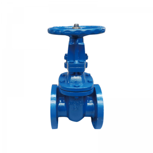
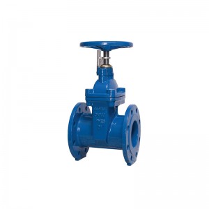
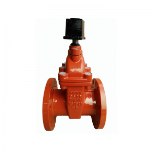
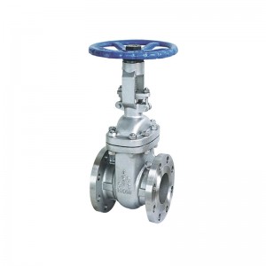
DIN3352 Resilient Seat Cast iron Gate Valve
DIN3352 Resilient Seat Cast iron Gate Valve
1.Standards: AWWA C515, DIN3352 F4/F5, BS5163, BS5150
2. Type: OS&Y,NRS
3. Size: DN50-DN600/2" - 24"
4. Material:CI,DI,STAINLESS STAIN,BRASS,BRONZE
5.pressure:CLASS 125-300/PN10-25/200-300PSI
6.Driving mode:handwheel,bevel gear,gear
DESCRIPTION
TECHNICAL REQUIREMENT :
● Design and Manufacture Conform to EN1171,DIN3352,EN1074
● Flange dimensions Conform to EN1092-2 PN16
● Face to Face dimensions Conform to EN558-1 Series 14, DIN3202 F5
● Testing Conform to EN12266, ISO5208
● Driving mode: hand wheel, square Nut
SPECIFICATION
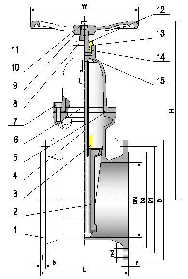
|
No. |
Part Name |
Material |
|
|
1 |
Body |
EN-GJS-500-7 |
|
|
2 |
Rubber Disc |
EPDM/NBR+DI. |
|
|
3 |
Stem Nut |
ZCuAl10Fe3 |
|
|
4 |
Stem |
1Cr17Ni2 |
|
|
5 |
Bonnet Gasket |
EPDM/NBR |
|
|
6 |
Bonnet |
EN-GJS-500-7 |
|
|
7 |
Socket Cap Screw |
Carbon Steel |
|
|
8 |
Seal Block |
ZCuZn40Mn3Fe1 |
|
|
9 |
Hand wheel |
EN-GJS-500-7 |
|
|
10 |
Nut |
Zinc-plated Carbon Steel |
|
|
11 |
Washer |
Zinc-plated Carbon Steel |
|
|
12 |
Dustproof Seal Ring |
EPDM/NBR |
|
|
13 |
O-ring |
EPDM/NBR |
|
|
14 |
O-ring |
EPDM/NBR |
|
|
15 |
O-ring |
EPDM/NBR |
F5 Dimensions data(mm)
|
DN |
50 |
65 |
80 |
100 |
125 |
150 |
200 |
250 |
300 |
350 |
400 |
450 |
500 |
600 |
|
L |
150 |
170 |
180 |
190 |
200 |
210 |
230 |
250 |
270 |
290 |
310 |
330 |
350 |
390 |
|
D |
165 |
185 |
200 |
220 |
250 |
285 |
340 |
405 |
460 |
520 |
580 |
640 |
715 |
840 |
|
D1 |
125 |
145 |
160 |
180 |
210 |
240 |
295 |
355 |
410 |
470 |
525 |
585 |
650 |
770 |
|
D2 |
99 |
118 |
132 |
156 |
184 |
211 |
266 |
319 |
370 |
429 |
480 |
548 |
609 |
720 |
|
b |
19 |
19 |
19 |
19 |
19 |
19 |
20 |
22 |
24.5 |
26.5 |
28 |
30 |
31.5 |
36 |
|
n-d |
4-19 |
4-19 |
8-19 |
8-19 |
8-19 |
8-23 |
12-23 |
12-28 |
12-28 |
16-28 |
16-31 |
20-31 |
20-34 |
20-37 |
|
f |
3 |
3 |
3 |
3 |
3 |
3 |
3 |
3 |
4 |
4 |
4 |
4 |
4 |
5 |
|
H |
226 |
265 |
288 |
320 |
364 |
410 |
502 |
596 |
681 |
810 |
905 |
1008 |
1135 |
1310 |
|
W |
200 |
200 |
200 |
255 |
255 |
306 |
306 |
360 |
360 |
406 |
406 |
508 |
508 |
508 |
F4 Dimensions data(mm)
|
DN |
50 |
65 |
80 |
100 |
125 |
150 |
200 |
250 |
300 |
350 |
400 |
450 |
500 |
600 |
|
L |
150 |
170 |
180 |
190 |
200 |
210 |
230 |
250 |
270 |
290 |
310 |
330 |
350 |
390 |
|
D |
165 |
185 |
200 |
220 |
250 |
285 |
340 |
405 |
460 |
520 |
580 |
640 |
715 |
840 |
|
D1 |
125 |
145 |
160 |
180 |
210 |
240 |
295 |
355 |
410 |
470 |
525 |
585 |
650 |
770 |
|
D2 |
99 |
118 |
132 |
156 |
184 |
211 |
266 |
319 |
370 |
429 |
480 |
548 |
609 |
720 |
|
b |
19 |
19 |
19 |
19 |
19 |
19 |
20 |
22 |
24.5 |
26.5 |
28 |
30 |
31.5 |
36 |
|
n-d |
4-19 |
4-19 |
8-19 |
8-19 |
8-19 |
8-23 |
12-23 |
12-28 |
12-28 |
16-28 |
16-31 |
20-31 |
20-34 |
20-37 |
|
f |
3 |
3 |
3 |
3 |
3 |
3 |
3 |
3 |
4 |
4 |
4 |
4 |
4 |
5 |
|
H |
226 |
265 |
288 |
320 |
364 |
410 |
502 |
596 |
681 |
810 |
905 |
1008 |
1135 |
1310 |
|
W |
200 |
200 |
200 |
255 |
255 |
306 |
306 |
360 |
360 |
406 |
406 |
508 |
508 |
508 |
Key Points of Construction and Installation of Forged Steel Gate Valve
The installation position, height, inlet and outlet direction must meet the design requirements, and the connection shall be firm and tight.
The handle of various manual valves installed on the insulation pipeline shall not be downward.
Visual inspection must be carried out before valve installation, and the nameplate of the valve shall comply with the provisions of the current national standard general valve mark gb12220. For valves whose working pressure is greater than 1.0MPa and which cut off the main pipe, strength and tightness tests shall be carried out before installation, and they can be used only after they are qualified.
During the strength test, the test pressure shall be 1.5 times of the nominal pressure, and the duration shall not be less than 5min. The valve shell and packing shall be qualified if there is no leakage. During the tightness test, the test pressure shall be 1.1 times of the nominal pressure; The test pressure shall meet the requirements of GB50243 standard during the test duration, and it is qualified if there is no leakage on the sealing surface of the valve disc.

