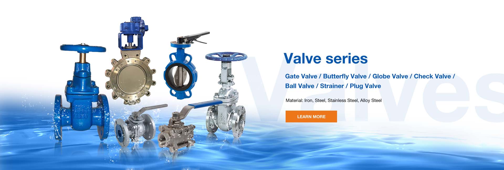
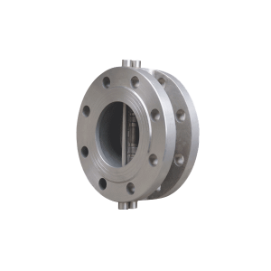
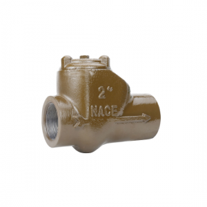
Double Disc Check Valve
Application
|
Technical Specification |
|
|
Design Standard |
API594 |
|
Face to face |
API594 |
|
Flanged ends |
ASME B16.5 |
|
Test & inspection |
API598 |
Note:the dimensions of connection ends can be desighed as per customers’requirements.
Specification
|
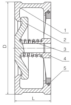
No. |
Part |
Material |
|
|
1 |
Body |
ASTM A216-WCB,ASTM A352-LCB ASTM A351-CF8,CF8M,CF8C,CF3,CF3M |
|
|
2 |
Disc |
ASTM A216-WCB,ASTM A352-LCB ASTM A351-CF8,CF8M,CF8C,CF3,CF3M |
|
|
3 |
Spring |
AISI9260,AISI6150 ASTM A182-F304,F316,F321,F304L,F316L |
|
|
4 |
Plate |
ASTM A216-WCB,ASTM A350-LF2 ASTM A351-CF8,CF8M,CF8C,CF3,CF3M |
|
|
5 |
Lock ring |
AISI9260,AISI6150 ASTM A182-F304,F316,F321,F304L,F316L |
Specification
|
No. |
Part |
Material |
|
1 |
Body |
ASTM A216-WCB,ASTM A352-LCB ASTM A351-CF8,CF8M,CF8C,CF3,CF3M |
|
2 |
Disc |
ASTM A216-WCB,ASTM A352-LCB ASTM A351-CF8,CF8M,CF8C,CF3,CF3M |
|
3 |
Spring |
AISI9260,AISI6150 ASTM A182-F304,F316,F321,F304L,F316L |
|
4 |
Plate |
ASTM A216-WCB,ASTM A350-LF2 ASTM A351-CF8,CF8M,CF8C,CF3,CF3M |
|
5 |
Lock ring |
AISI9260,AISI6150 ASTM A182-F304,F316,F321,F304L,F316L |
Dimensions and Weights CLASS150-900
|
Pressure |
CLASS 150 |
CLASS 300 |
|||||||||||||||||||||
|
Size |
mm |
15 |
20 |
25 |
32 |
40 |
50 |
65 |
80 |
100 |
125 |
150 |
15 |
20 |
25 |
32 |
40 |
50 |
65 |
80 |
100 |
125 |
150 |
|
in |
1/2 |
3/4 |
1 |
11/4 |
11/2 |
2 |
21/2 |
3 |
4 |
5 |
6 |
1/2 |
3/4 |
1 |
11/4 |
11/2 |
2 |
21/2 |
3 |
4 |
5 |
6 |
|
|
L(mm) |
16 |
19 |
22 |
31.5 |
31.5 |
40 |
46 |
50 |
60 |
90 |
106 |
25 |
31.5 |
35.5 |
40 |
45 |
56 |
63 |
71 |
80 |
110 |
125 |
|
|
H(mm) |
47 |
57 |
66 |
85 |
85 |
103 |
122 |
135 |
173 |
196 |
222 |
53 |
65 |
72 |
81 |
95 |
110 |
129 |
148 |
180 |
215 |
250 |
|
|
Weight(Kg) |
0.2 |
0.3 |
0.45 |
0.8 |
0.8 |
1.2 |
2.3 |
3 |
7 |
12 |
15 |
0.23 |
0.36 |
0.52 |
0.75 |
1.1 |
1.95 |
2.9 |
5.5 |
9 |
15 |
20 |
|
|
Pressure |
CLASS 600 |
CLASS 900 |
|||||||||||||||||||||
|
Size |
mm |
15 |
20 |
25 |
32 |
40 |
50 |
65 |
80 |
100 |
125 |
150 |
15 |
20 |
25 |
32 |
40 |
50 |
65 |
80 |
100 |
125 |
150 |
|
in |
1/2 |
3/4 |
1 |
11/4 |
11/2 |
2 |
21/2 |
3 |
4 |
5 |
6 |
1/2 |
3/4 |
1 |
11/4 |
11/2 |
2 |
21/2 |
3 |
4 |
5 |
6 |
|
|
L(mm) |
25 |
31.5 |
35.5 |
40 |
45 |
56 |
63 |
71 |
80 |
110 |
125 |
25 |
31.5 |
35.5 |
40 |
45 |
56 |
63 |
71 |
80 |
110 |
125 |
|
|
H(mm) |
53 |
65 |
72 |
81 |
95 |
110 |
129 |
148 |
192 |
240 |
265 |
63 |
69 |
78 |
88 |
98 |
142 |
164 |
167 |
205 |
247 |
288 |
|
|
Weight(Kg) |
0.25 |
0.38 |
0.55 |
0.8 |
1.2 |
2 |
2 |
6 |
10 |
17 |
22 |
0.3 |
0.4 |
0.6 |
1 |
1.5 |
2.5 |
4 |
8 |
13 |
20 |
25 |
|
When the check valve is installed on the pipeline, it becomes one of the fluid components of the complete pipeline. The opening and closing process of the valve disc is affected by the transient flow state of the system in which it is located; In turn, the closing characteristics of the valve disc have an effect on the fluid flow state. The working characteristics of the check valve are large load change and small opening and closing frequency. Once it is put into the closed or open state, the service cycle is very long, and the moving parts are not required to move. However, once there is a switching requirement, it must move flexibly, which is more stringent than the common mechanical movement. In most practical applications, the check valve is qualitatively determined to be used for rapid closing, and at the moment when the check valve is closed, the medium flows in the opposite direction. With the closure of the valve disc, the medium quickly decreases from the maximum backflow speed to zero, while the pressure increases rapidly, that is, a "water hammer" phenomenon that may damage the pipeline system. For the high-pressure pipeline system with multiple pumps in parallel, the problem of water hammer of check valve is more prominent. Water hammer is a kind of pressure wave in transient flow in penstock. It is a hydraulic shock phenomenon of pressure rise or fall caused by the change of fluid velocity in penstock. The physical reason is the combined action of fluid incompressibility, fluid motion inertia and pipeline elasticity. In order to prevent the hidden danger of water hammer in the pipeline, over the years, people have adopted some new structures and materials in the design of check valve. Gratifying progress has been made in minimizing the impact force of water hammer while ensuring the applicable performance of check valve.


